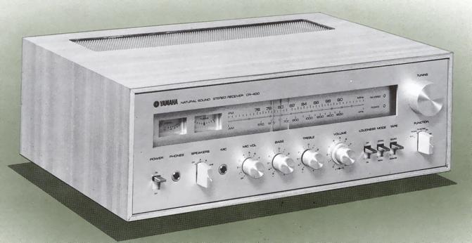
YAMAHA CR-400
¥ 59,000 (around 1974)
Commentary
A stereo receiver that emphasizes high sensitivity and cost performance.
The main amplifier section uses a pure complimentary service OCL circuit directly connected to all stages, and the first stage differential amplifier uses an FET as a constant current source to provide sufficient negative feedback for high stability.
The circuit of the main amplifier also serves as an active subsonic filter, and signals below 20 Hz (3 dB down point) are cut at a slope of 12dB/oct.
The equalizer amplifier uses a 3-stage direct-coupled monolithic IC to achieve high stability, low distortion factor and high gain, while the equalizer element uses high-quality parts to improve its characteristics.
The トーンオ K-to-roll circuit adopts Yamaha's original NF type, which applies negative feedback between the collector and emitter of a 2-stage direct-coupled amplifier. This circuit has good control characteristics and low distortion.
The microphone mixing circuit is equipped with a 3-chip dedicated amplifier independent of other program sources.
You can also record the mixed signal to tape using the Pre-out jack.
The FM tuner section uses a low-noise FET and 3-series variable capacitor in the front end, a differential amplifier IC with good limiter characteristics and ceramic filter in the IF stage, and a dedicated IC in the MPX circuit to achieve high sensitivity and high selectivity.
Since the AM tuner section is designed with an emphasis on sound quality, it realizes AM reception with less interference and beat with adjacent stations and without distortion.
Uses a 2-meter system for signal and tuning.
It is equipped with two FM antenna terminals, an FM muting circuit and a loudness switch.
Model Rating
| Type | Stereo receiver |
| <Audio section> | |
| Effective output (0.5% distortion factor) | 16W + 16W (8 Ω, double-channel drive, 20 hz to 20 khz) 18W + 18W (8 Ω, both channel drive, 1 khz) 20W/20W (8 Ω, single-channel drive, 1 kHz) |
| Dynamic Power | 56W or More (IHF, 8 Ω) |
| Total harmonic distortion rate (20 Hz to 20 kHz) | 0.5% or Less (Effective Output) 0.1% or Less (at 1W Output) |
| Cross modulation distortion factor | 0.1% or Less (70 Hz : 7 kHz = 4 : 1, Effective Output) |
| Power Bandwidth (IHF, 0.5% distortion factor) | 15 Hz to 50 kHz |
| Frequency characteristic | Phono (RIAA deviation) : 30 Hz to 15 kHz ± 0.7 dB Mic : 100 Hz to 10 kHz + 0.5 -6dB Aux : 20 Hz to 50 kHz + 0. 5-3 dB |
| Damping factor | 40 (1 kHz, 8 Ω) |
| Input Sensitivity / Impedance (1 kHz, effective output) |
Phono : 3mv/50k Ω Mic : 3mV/50k Ω Aux, Tape PB : 150mV/100k Ω |
| Phono maximum allowable input (0.5% distortion factor) | 135mVrms |
| MIC Maximum Allowable Input (Distortion Factor 0.3%) | 450mVrms |
| Output Level / Impedance | Rec out : 150mV/10k Ω Pre-out : 200mV/3k Ω |
| Tone control | Bass : ± 10 dB (50 Hz) Treble : ± 10 dB (10 kHz) |
| S/N (IHF, A Network) | Phono:72dB Mic:60dB Aux, Tape PB : 85 dB |
| FM Tuner Section | |
| Receiving frequency | 76 MHz to 90 MHz |
| Practical Sensitivity (IHF, 84 MHz) | 2.5 μ V |
| Image interference ratio (84 MHz) | 55dB |
| IF Interference Ratio (84 MHz) | 75dB |
| Spurious interference ratio (84 MHz) | 75dB |
| AM suppression ratio | 50dB |
| Capture ratio | 2.0dB |
| Effective selectivity (IHF) | 65dB |
| S/N | 68dB |
| Total harmonic distortion factor | Mono : 0.3% or less Stereo : 0.8% or less (400 Hz) |
| Stereo Separation (400 Hz) | 40 dB or more |
| Frequency characteristic | 50 Hz to 10 kHz ± 1.0 dB |
| <AM Tuner Section> | |
| Receiving frequency | 525 kHz to 1605 kHz |
| Practical sensitivity | 52dB/m (IHF, bar antenna) 25 μ V (external antenna) |
| S/N(80dB/m) | 43dB |
| Image interference ratio (1000 kHz) | 45dB |
| IF Disturbance Ratio (1000 kHz) | 40dB |
| Selectivity (1000 kHz) | 25dB |
| <General> | |
| Semiconductor used | Transistor : 38 FET : 3 Diode : 22 pcs Zener diode : 1 unit Light Emitting Diode : 2 IC : 4 |
| Power consumption | 80W (rated) 130W maximum |
| AC outlet | Switched:200W Unswitched:200W |
| External dimensions | Width 444x Height 158x Depth 300 mm |
| Weight | 9.5kg |