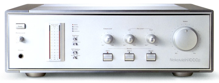
Nakamichi 1000p
¥ 550,000 (around 1989)
Commentary
The D/A converter was developed in combination with the Nakamichi1000 DAT deck in pursuit of the highest sound quality beyond the highest analog deck.
The digital filter uses a 20-bit 8 x oversampling digital filter.
The D/A conversion section uses a 20-bit full calibration D/A conversion system.
This circuit uses three key technologies : digital ROM calibration, tandem 20-bit converter, and glitch eraser to achieve extremely high conversion accuracy and extremely low distortion rate at the theoretical limit.
In digital ROM calibration, all bits are digitally corrected by a calibrated ROM that stores correction data for each D/A converter IC. This prevents characteristic changes due to time and temperature, and realizes extremely high conversion accuracy.
Calibration and writing data to the ROM are performed for each unit at the time of shipment from the factory. First, a 22-bit A/D converter for measurement is connected to a 1000p test point in operation to accurately measure the D/A conversion error. Then, the subtle peculiarities of each converter IC are grasped by special arithmetic processing assuming all situations. Then, this error data is written in the ROM, which is mounted on the D to A converter circuit board of each unit. Unlike analog methods such as semi-fixed resistors, the ROM directly adjusts digital data to achieve complete accuracy correction.
This circuit completely eliminates the slight noise associated with the original sound, which could not be eliminated by conventional D/A conversion.
In the tandem 20-bit converter, the 20-bit output of the digital filter is first divided into upper 14 bits and lower 6 bits, then processed by a dedicated 16-bit D/A converter and digitally added again to achieve 20-bit operation. Each D/A converter operates with a sufficient margin. For the lower 6 bits, which require particularly high precision, only the high-order bits of the 16-bit converter are used to achieve linear conversion. For the upper 14 bits, a margin of 2 bits is left to ensure conversion accuracy.
Complete accuracy correction by digital ROM calibration has achieved the 20-bit limit performance.
In a typical D/A converter, a signal contaminated by glitch noise is sent directly to an analog circuit, where the glitch is removed (sampled and held) in an analog manner. However, in this method, the switching noise of the sample-and-hold circuit itself masks a small signal of 60 to 80 dB, making it difficult to reproduce music accurately.
In order to eliminate this glitch noise at the digital data stage, it is equipped with a glitch eraser originally developed by Nakamichi. In this circuit, in order to eliminate the very minute glitch noise at each bit transition except for the 0 cross point, which has been considered as a problem until now, every occurrence point of the glitch is predicted in advance, and it is completely cancelled out, realizing an ultra-low distortion rate of 0.0015% which is the theoretical limit.
The A/D converter uses a sample hole dressing auto-calibration A/D converter.
In this circuit, the charge comparison method, the state-of-the-art A/D conversion method at that time, has been put into practical use for audio applications. By using the charge to weight each bit, the sample-and-hold circuit, which was the cause of sound quality degradation in A/D conversion, is eliminated.
In addition, high-precision A/D conversion has been realized by the adoption of an auto-bit calibration system that automatically calibrates the weighting accuracy of each bit and a 16-bit 2 x oversampling digital filter.
The Autobit Calibration System starts automatically when the power is turned on and is tuned to nearly perfect 16-bit accuracy in 1.4 seconds using a digital tuning method to prevent accuracy degradation due to aging.
It employs a twin PLL stabilized interface, and Nakamichi's unique digital data stabilizer and two PLLs shut out disturbances such as jitter superimposed on digital signals.
Equipped with a 32-dot peak level meter that reads digital data directly.
This meter is a professional specification ultra-high precision type with an error limit of ± 0.2 dB. The discrete driving circuit and dedicated LSI enable full static lighting without adversely affecting sound quality.
This meter has a peak hold function and a meter off function.
The audio circuit uses a fully balanced discrete transmission system.
A multi-power supply is used for the power supply section to eliminate mutual interference between stages, and an isolated ground system to eliminate mutual interference via ground.
Resonance braking structure is adopted.
Uses a full static indicator.
Equipped with analog level volume.
Two types of digital input / output terminals are mounted : coaxial and optical.
Equipped with DAT mutual copy function.
Equipped with a headphone terminal with dedicated level volume.
It is equipped with an emphasis switch.
LC-OFC Class 1 audio cable is included.
There was a business model with almost the same contents except for some specifications.
.jpg)
.jpg)
.jpg)
.jpg)
.jpg)
Model Rating
| Type | D/A converter (digital audio processor) |
| D/A Converter Section (Measured at 44.1 kHz) | |
| Method | 20-bit full-calibrated D/A converter 20-bit 8 x oversampling digital filter |
| Sampling frequency | 48 kHz, 44.1 kHz, 32 kHz |
| Frequency characteristic | 5 Hz to 20 kHz ± 0.5 dB |
| Signal-to-noise ratio | 106 dB or more |
| Dynamic range | 100 dB or more |
| Total harmonic distortion factor | 0.0005%(1kHz) |
| Total harmonic distortion factor and noise | 0.0015%(1kHz) |
| Channel separation | 106 dB or more |
| A/D Converter Section (Sampling Frequency 48 kHz, Measured at A/D → D/A) | |
| Method | 16-bit autocalibration A/D converter 16-bit Double Oversampling Digital Filter |
| Sampling frequency | 48kHz |
| Frequency characteristic | 5 Hz to 22 kHz ± 0.5 dB |
| Signal-to-noise ratio | 95 dB or more |
| Dynamic range | 95 dB or more |
| Total harmonic distortion factor | 0.001%(1kHz) |
| Total harmonic distortion factor and noise | 0.003%(1kHz) |
| Channel separation | 85 dB or more |
| <Input / Output Unit> | |
| Digital input | 75 Ω Coaxial / Optical (switching) x3 |
| Digital output | 2 x 75 Ω coaxial / optical (parallel) |
| Line input | Equilibrium : 50 mv (-18dB, maximum Rec level) / 40k Ω Unbalanced : 50 mv (-18dB, maximum Rec level) / 25k Ω |
| Line output (balanced) | Fixed : 2 v (0 dB) / 100 Ω Variable : 2 V (0 dB, maximum output level) / 100 Ω |
| Line output (unbalanced) | Fixed : 2 v (0 dB) / 1k Ω Variable : 2 v (0 dB, Ouput level maximum) / 1k Ω |
| Headphone out | 100 mW (0 dB, Phones level maximum) / 40 Ω |
| <General> | |
| Pwer | 100 VAC, 50Hz/60Hz |
| Power consumption | 70W max. |
| External dimensions | Width 435x Height 133x Depth 370 mm |
| Weight | Approx. 17.5 kg |