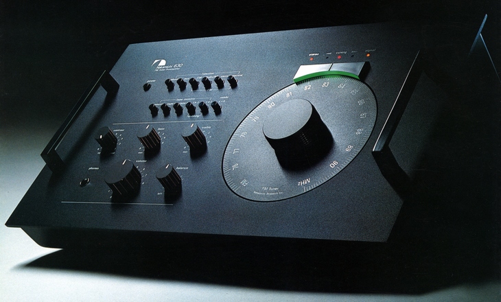
Nakamichi 630
¥ 148,000 (around 1977)
Commentary
This 600 series FM tuner preamplifier combines the functions of an FM tuner and a control amplifier.
Amplifier section
The preamp section of the 630 inherits almost the same circuit and performance of the 610.
The basic circuit configuration uses a triple transistor circuit.
This circuit focuses on the problem of the thermal noise en caused by the base input resistance hie of the transistor. In an actual circuit, the source impedance Rs is added to hie in series. In this case, the value of Rs is larger than hie, so the thermal noise generated by Rs is often larger than hie. Therefore, the value of en tends to be ignored. However, the effect of hie on the signal-to-noise ratio is large when Rs is very small, such as MC-type cartridges.
To solve this problem, we have adopted a triple transistor circuit that reduces the hie by one third and the en by one third. Furthermore, we have improved the S / N ratio by approximately 10 dB by adopting a transistor with less current noise in.
Both the first stage and the second stage are common-emitter amplifiers, and a complimentary service class A push-pull circuit is used for the output stage. Usually, a differential amplifier is used because it is easy to construct an NF circuit for a preamplifier. However, a buffer amplifier is used for all preamps to avoid non-linear distortion due to the internal resistance of the differential transistor at low volume and noise accumulation.
In a differential amplifier, the differential transistor outside the NF loop has an internal resistance Ri. This resistance Ri varies with the level. Nonlinear distortion occurs when Ri becomes larger than the resistance inside the NF loop at a low volume. In a circuit of 630, the differential transistor can be assumed to be removed, and Ri becomes 0 so that the playback sound is not affected by the level change.
Equipped with a high output headphone amplifier.
When inserted into the headphone jack, the pre-out output is automatically cut.
Metal film resistors and high-precision capacitors, which are more expensive than transistors, are frequently used, and all printed circuit boards are made of epoxy plastic.
In addition, the part layout has been made to have very little effect of flux by taking advantage of the experience accumulated over 10 years ago.
Equipped with a phono input sensitivity selector switch, 3-step switching is possible so that it can be adjusted to the output of the cartridge.
Impedance is 100k Ω constant and direct connection of MC type cartridge is also possible.
Equipped with two types of tape monitor and dubbing switch.
Equipped with contour volume as a loudness function.
This circuit differs from conventional ones in that the compensation amount of frequency balance is automatically changed as the volume is reduced.
FM tuner section
The IF stage employs a 2-step switching of selectivity, which can be switched according to the reception condition.
A 12-element LC filter is used lc filter is used, but by integrating 6 elements into one pack, the reduction in distortion rate is effectively limited to two stages of filter. normal position
In the narrow band, a four element ceramic filter with excellent spurious characteristics is made into one element on one wafer, and combined with two stages of LC linear phase filter to make a three stage configuration. Moreover, one pack is made into an IC-like shipping system that mutually cancels the influence of thermal characteristics, characteristic differences of elements, and disturbance.
The front-end section employs a frequency-linear 5-row variable capacitor developed exclusively for FM. This improves the selection characteristics by multi-stage tuning and suppresses gain deviation by adopting a triple-tune configuration.
For RF amplification, a low-noise dual-gate MOS-FET is used. Because of its low distortion, high-order harmonic generation is suppressed, and it has excellent ability to eliminate intermodulation interference and intermodulation interference. Because of its low-noise element, it also has sufficient practical sensitivity.
The front end part is grounded on a metal plate at the shortest distance to prevent the leakage of local oscillation frequency and other interference. The metal plate has a temperature coefficient several times higher than that of printed circuit boards, which prevents various types of drift.
In addition, the front end, RF-stage and IF-stage are completely shielded by 1 mm thick tinning steel plates to prevent spurious generation due to beat interference caused by clips.
Digital tuning method is adopted for tuning method.
When the left lamp of the tuning indicator at the top of the tuning dial lights up, it indicates that the tuning point is shifted to the right. When the right lamp lights up, it indicates that the tuning point is shifted to the left. When the center lamp lights up, it is an accurate tuning point.
In addition, this lamp also serves as an indicator of the input level of radio waves. It lights up at approximately 30 dBf (17 μ V300 Ω), and the signal indicator shows the strength of the input level of radio waves. It operates at approximately 55 dBf (300 μ V300 Ω). When it lights up, S/N and distortion factor are guaranteed.
In this tuning operation, the lighting level is narrowed with a sharp range of 25 kHz selectivity, and once tuned, the range is widened to 50 kHz width to absorb slight tuning drift and improve sound quality.
A PLL circuit is used in the MPX section.
As a result, the phase shift of the MPX signal generated inside the tuner due to the influence of heat and humidity is detected, and the phase is corrected so that it is always in the same phase, resulting in stable separation.
It is equipped with a muting mechanism to eliminate inter-station noise during channel selection.
Muting is linked with the tuning indicator logic and is released when the red light in the center comes on.
Equipped with an MPX filter that cuts the 19 khz pilot signal.
Conventional filters tend to cut down to the audible frequency band around 15 kHz, resulting in poor sound quality. Therefore, in the 630, we devised and adopted a filter with a unique attenuation curve that provides a sharp attenuation curve from 18 kHz.
At 19 kHz, the attenuation is -70dB and the distortion is 0.03% or less, reducing the effect on the original frequency characteristics of FM broadcast waves.
To support Dolby FM broadcasting, a Dolby FM decoding circuit is mounted.
There was a special rack for 600 series as an option sold separately.
This rack is specifically designed for the 600 series and can be used to mount the configuration of your choice.
.jpg)
.jpg)
.jpg)
.jpg)
.jpg)
Model Rating
| Type | FM tuner control amplifier | ||
| Preamplifier Section | |||
| Input Sensitivity / Impedance | Phono : 1 mV, 2 mV, 5mV/100k Ω Aux, Tape mon1/2 : 100mV/50k Ω |
||
| Maximum input level | Phono : 250 mV (at 1 kHz, sensitivity selector switch 5 mV) | ||
| Output level / impedance / load impedance | Pre out : 1V/500 Ω / 10k Ω Rec out : 100mV/1k Ω / 50k Ω Headphone : 40mV/4.5 Ω / 8 Ω |
||
| Maximum power output | Pre-out : 5V/50k Ω Rec out : 4V/50k Ω Headphone : 300mW/8 ohm |
||
| Frequency characteristic | Phono (RIAA deviation) : 30 Hz to 15 kHz ± 0.3 dB Aux, Tape mon1/2 : 20 Hz to 50 kHz + 0 -1.5 dB |
||
| S/N ratio (IHF-A network) / input conversion ratio | Phono : 80 dB or More / -140dB (when sensitivity selector switch is 1 mV) Aux, Tape mon : 102 dB or more / -122dB |
||
| Residual Noise Level (IHF-A Network) | Pre-out : 4 μ V or less (Vol. min) Headphone : 8 μ V or less (8 Ω) |
||
| Distortion Factor (Vol. max, output2V) | Phono : 0.003% or less (10 kHz or less) Aux, Tape mon : 0.004% or less (10 kHz or less) |
||
| Tone control | Bass : ± 9 dB (20 Hz) Treble : ± 9 dB (20 kHz) |
||
| contour (Vol. "8") | -30dB(3kHz) -15dB(20Hz) -24dB(20kHz) |
||
| Tuner Section | |||
| Receiving frequency | 76 MHz to 90 MHz | ||
| Practical sensitivity | 3 μ V (12.5 dBf) 300 Ω | ||
| Distortion Factor (1 kHz, 100% Modulation) |
|
||
| Signal-to-noise ratio (IHF) | Dolby NR system out Mono : 70 dB or higher Stereo : 68 dB or higher Dolby NR system in Mono : 75 dB or higher Stereo : 73 dB or more |
||
| Frequency characteristic | 50 Hz ~ 15 kHz + 0.3 -1.5 dB | ||
| Effective selectivity (IHF) | Normal : 40 dB or more Narrow : 80 dB or more |
||
| Stereo separation |
|
||
| Capture Ratio (IHF) | 1dB(Normal) | ||
| Image interference ratio | 100 dB or More (82 MHz) | ||
| IF interference ratio | 100 dB or more | ||
| Spurious interference ratio | 100 dB or more | ||
| SCA suppression | 75dB | ||
| AM suppression | 60dB | ||
| MPX Filter | 19 kHz, -70dB | ||
| Antenna terminal | 300 Ω balance 75 Ω unbalance |
||
| Tuner out | 0.1 v (50% modulation) | ||
| <General> | |||
| Power supply voltage | 100 VAC, 50Hz/60Hz | ||
| Power consumption | 20VA | ||
| External dimensions | Width 400x Height 170x Depth 237 mm | ||
| Weight | Approx. 7 kg | ||
| Sold Separately | 600 Series Embedded Rack SYSTEM-ONE (¥ 25,000) | ||
.jpg)
.jpg)