DENON POA-3000
¥ 350,000 (released in 1979)
Commentary
This is a stereo power amplifier equipped with DENON class A, which was created by thoroughly investigating class A operation.
Equipped with DENON Class A by DENON's unique real bias circuit, it realizes high output while operating as A class amplifier.
The output transistor is a newly developed high-speed power transistor (f) with particularly excellent high-frequency characteristics.T: 100 MHz, Pc : 150W). This transistor can be operated at high power.FEIt has good linearity and can maintain the rated output with low distortion even at 100 Hz.
This high-speed power transistor has five parallel push-pull connections per channel, dramatically improving linearity and achieving low-distortion characteristics over a wide bandwidth.
A real bias circuit has been adopted to solve the problems of low efficiency, heat generation and large size which were the defects of A class amplifier.
Because this circuit performs class A linear amplification using the linear region of the amplification characteristics of the transistor without distortion of the signal waveform, it is controlled so that a DC bias current equal to the peak value of the signal current flowing in the transistor is supplied. This allows a stable and appropriate DC bias current to be supplied according to the magnitude of the signal waveform from a small signal to a large signal, saving power consumption and reducing heat generation. In addition, since the bias current is stably controlled by the control function regardless of the temperature condition of the output transistor, the operating state of the best condition is always maintained.
In addition, the bias current is controlled to rise earlier than the signal current. In order to prevent the delay cutoff of the rise of the bias at this time, a small fixed bias current is supplied even when there is no signal, so that the bias rises one step ahead of the rise of the signal. Thus, even when a high-frequency musical tone signal with a fast rise comes, the bias rises earlier and increases, so that the operation is controlled to ensure class A operation.
In addition, the fixed bias current effectively acts on the non-linear characteristics of the transistor in the small current region, and the output transistor is controlled so that it does not enter this region.
This real-bias circuit realizes an efficiency of approximately 1/5 power consumption compared with conventional systems.
The driver circuitTA small-signal transistor (f) having a high linearity characteristic is provided.T(400 MHz, Pc : 400 mW) are connected in parallel for each channel.
F of the putter transistorTThe cascode connection of this transistor, which has four times the wide-band transmission characteristic of the transistor, further improves the high-band linearity, prevents the influence of the Cob (collector-base junction capacitance) of power transistors, etc., and prevents the degradation of the high-band characteristic by driving the output stage with a wide-band and low impedance.
Power is supplied from a power supply circuit independent of the final output stage to prevent mutual interference.
The pre-driver stage is balanced by a twin complimentary service differential circuit and the power stage is push-pull driven by a cascode pre-driver.
The transistor used is the same f as the driver stage.TA high-speed transistor of 400 MHz is adopted, and a drive circuit capable of power drive is constructed for wide-band and low-impedance amplification.
In addition, in order to maintain the stability of the operating point of differential circuits such as pre-drivers, an operation stabilizer circuit is installed to suppress the effect of temperature drift.
The first stage employs a low-noise FET differential amplifier and a direct DC servo system that operates in parallel.
This is the same configuration as the control amplifier PRA-2000. It is not only a servo to eliminate unnecessary coloring by removing the coupling capacitor of the input part and to obtain stability in the ultra-low range by simply shutting out DC mid-point drift. Since no servo amplifier is added to the feedback system, the noise level does not increase. By connecting differential amplifiers in parallel and DC servo to each amplifier, the noise is reduced by 3 dB and the distortion rate is improved to 1/2.
The power supply section uses a separate power transformer system for the output stage and others.
The power supply for the output stage consists of a large toroidal transformer with separate left and right windings and a 100,000 μ F large-capacity capacitor with low impedance up to the high frequency range. This transformer has a capacity (1000 VA) approximately twice that of a 200W + 200W B-class amplifier power supply transformer. This transformer is floated in a non-magnetic 2 mm thick aluminum chassis to prevent magnetic distortion.
From the first stage to the drive stage, an EI-type power transformer is installed separately to avoid the effect of severe load fluctuation of the output stage. A constant voltage stabilizing circuit is provided to stabilize the power supply and reduce impedance.
To prevent an extremely large inrush current (inrush current) when the power switch is turned on from shortening the life of the power switch or affecting other electrical appliances, we have installed an inrush prevention circuit in the power supply part to prevent troubles.
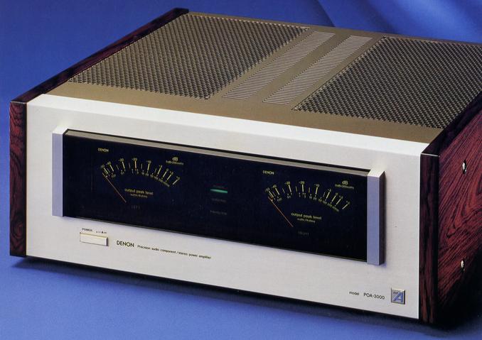
Equipped with a large power meter that can directly read the left and right output levels in dB and W.
The speakers and transistors are protected by a high-speed protection circuit that also serves as a muting circuit to prevent pop noise that occurs when the power switch is turned ON / OFF.
When an error occurs, the protection indicator LED in the front glass flashes.
The internal layout of the amplifier is symmetrical, and the power supply part is located away from the first stage circuit as far as possible in terms of position and electrical. The construction gives priority to characteristics.
The the meter section of the front panel, thick flat glass is used for the overlay effect and mirror effect. When the power is turned on, the DENON mark is displayed for five to six seconds and then a large peak meter is illuminated.
Mirror finish is applied to the side plate.
.JPG)
.JPG)
.JPG)
Model Rating
| Type | Stereo power amplifier |
| Music power | 250W + 250W (8 Ω) |
| Rated Output (Double-channel Drive, Sine Wave Output, 20 Hz to 20 kHz) | 180W + 180W (8 Ω) |
| Total harmonic distortion factor | 0.002% or Less (20 Hz to 10 kHz) 0.003% or Less (20 Hz to 20 kHz) |
| Intermodulation Distortion Factor (60 Hz : 7 kHz = 4 : 1, Rated Output) | 0.003% or less (at 180W equivalent) |
| Output Bandwidth (IHF, both channel drives) | 5 Hz ~ 100 kHz (THD 0.02%) |
| Input Sensitivity / Input Impedance | 1V/50k Ω |
| Output impedance | 0.04%(1kHz) |
| Damping factor | 200 (8 Ω, 1 kHz) |
| S/N ratio (IHF-A) | 122 dB or more |
| Transmission characteristic | 1 Hz ~ 350 kHz + 0 dB -3dB |
| Separation | 100 dB or More (20 Hz to 1 kHz) 85 dB or More (~ 20 kHz) |
| Slew rate | ± 300 V / μ sec or more |
| Frequency characteristic | 10 Hz to 100 kHz ± 3 dB |
| Subsonic filter characteristics | 16 Hz, 6dB/oct. |
| Level meter characteristic | Indication method : peak value indication method output level meter Indication Range : -50dB to + 5 dB, 0 dB = 200W/8 Ω |
| Power supply voltage | 100 VAC, 50Hz/60Hz |
| Power consumption | No signal : 220W Signal : 730W (Electrical Appliance and Material Control Law) |
| External Dimensions (Including Knob and Leg) | Width 495x Height 188x Depth 459 mm |
| Weight | 34kg |